The PCA9685 is pulse width modulation control IC. It can handle up to 16 PWM channels with 12 bit resolution. For initial development and testing the PCA9685 is driving LEDs but I plan to use this to drive servo motors as well.
Version 0.1 of my flight controller board includes a PCA9685 to experiment with offloading servo control. Previously, I used the ATmega4809 timers and GPIO pins to directly drive servo motors. By using the PCA9685, I can offload work from the ATmega4809 to free up its resources for other things. The main goal of this project is to get the ATmega4809 talking to the PCA9685 over I2C and do some initial tests dimming LED lights.
All of this was done with an ATmega4809 MCU on the Wingboard v0.1 custom PCB. The firmware was developed using MPLAB IDE & programmed with a PICkit 4. The source code for this test can be found in my atmega4809-stuff repo.
PCA9685 Hardware Setup
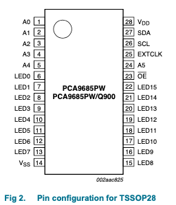
Here is the PCA9685 pinout from the NXP data sheet along side part of the schematic of the PCB used in this test.
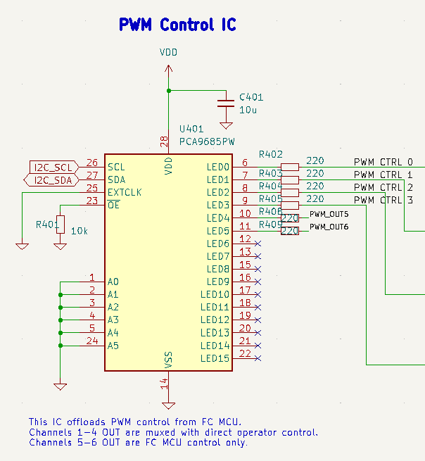
I have the pins connected as follows:
- A0 to A5 pins tied to ground (making the I2C address 0x40)
- LED0 to LED5 tied to my PWM out pins
- LED6 to LED15 are flapping in the breeze (not connected)
- VSS Tied to ground
- VDD tied to 5v power rail
- SDA & SCL each tied to ATmega4809 SDA & SCL with 10K pullup resistors.
- External Clock tied to ground (not used)
- Inverted Output Enable tied to ground (always enabled)
Side Note About PCA9685 & I2C Libraries
In the current MPLAB X IDE (v6.00), I do not see a way to have a library project reference another library project. So my PC9685 library could not reference my I2C library. To work around this limitation I created a struct called I2cFunctions in PCA9685 which contains pointers for the I2C functions that are needed. The I2cFunctions struct must be populated and passed (by pointer) into every PCA9685 function call.
typedef struct I2cFunctions {
    void (*f_I2cInitialize)();
    void (*f_I2cWriteByte)(uint8_t addr, uint8_t reg, uint8_t value);
    void (*f_I2cWriteBytes)(uint8_t addr, uint8_t reg, uint8_t *value, uint8_t length);
} I2cFunctions;

void SetupPca9685(I2cFunctions *i2c_functions);
void SetLed(I2cFunctions *i2c_functions, uint8_t led_number, uint16_t pulse_width_ticks);
void RunPca9685LightTest(I2cFunctions *i2c_functions);
The function pointers are set in the main project code by including both the PCA9685 and I2C library, instantiating an I2cFunctions struct, and assigning I2C functions to the struct fields.
#include "../PCA9685.X/PCA9685.h"
#include "../I2C.X/i2c.h"
...
I2cFunctions i2c_functions;
...
i2c_functions.f_I2cInitialize = I2cInitialize;
i2c_functions.f_I2cWriteByte = I2cWriteByte;
i2c_functions.f_I2cWriteBytes = I2cWriteBytes;
PCA9685 Register Configurations
The essential PCA9685 registers to configure at startup are MODE1, MODE2, and PRE_SCALE. After some trial and error (and looking at some other PCA9685 libraries) I created an initialization routine that seems to work well.
- Set MODE1 to restart, leaving in sleep mode, and setting auto-increment
- Set PRE_SCALE register (must be done while sleep mode is enabled)
- Set MODE1 to disable sleep mode
- Set MODE2 to enable the output driver
This is all done in the SetupPca9685() function of the PCA9685 library. Here is a capture of the I2C traffic doing the setup.

Calculating PRE_SCALE Value
The PCA9685 can use an external clock source or its internal 25MHz clock. In this example, the PCA9685 is set to use the internal clock. The PWM period is based on the clock rate and the PRE_SCALE register value. The PRE_SCALE value can be calculated for the desired PWM frequency using this equation.
PRE\_SCALE = round[\frac{F_{CLK}}{4096 * F_{PWM}}] - 1For example, if I want the PWM frequency to be 50Hz when using the 25MHz clock, then using the equation above I calculate that the PRE_SCALE register should be set to 121.
PRE\_SCALE = round[\frac{25*10^6}{4096 * 50}] - 1 \\ \ \\
= round[121.0703125] = 121
… Except that when I actually set PRE_SCALE to 121 and measure the PWM output with a logic analyzer, I measure a frequency of ~53.2Hz, which is a bit off of 50Hz. This is probably due to inaccuracy with the internal clock. To get closer to 50Hz, I tested different PRE_SCALE values and measured until I found the one that got the closest to 50Hz. For this particular chip, the best PRE_SCALE value for running at 50Hz is 129.
Here are the test values that I used and the resulting PWM period error. The goal is to get a period of 20ms, which corresponds to a frequency of 50Hz.
| PRE_SCALE Value | Measured Period | Error |
|---|---|---|
| 121 | 18.8 ms | 1.8 ms |
| 125 | 19.4 ms | 0.6 ms |
| 128 | 19.894 ms | 0.106 ms |
| 129 | 20.054 ms | 0.054 ms |
The 50Hz PWM frequency is necessary for servo motor control, but will cause flicker when dimming LED lights. So for driving LEDs in this test I set PRE_SCALE to the minimum value of 3 which should put the PWM frequency up around 1526Hz.
* Note that PRE_SCALE can only be changed while PCA9685 sleep mode is enabled.
Setting PWM Values
The duty cycle of each PWM pin is controlled by setting ON & OFF register values which are compared with the value of a free-running 12-bit counter (0 to 4095). When the counter value matches the ON register value of an LED, that pin is set HIGH. Similarly, when the counter value matches the OFF register value, the corresponding LED pin is set LOW.
The ON and OFF values for an LED are set by writing to 4 dedicated registers for that LED called: LED_n_ON_L, LED_n_ON_H, LED_n_OFF_L, LED_n_OFF_H. Each LED has it’s own set of these 4 registers. The ON & OFF compare values are 12-bit values, so the 4 most significant bits of each high byte are ignored.
To make things simple in this test, I set the ON values all to zero and update the OFF value for each LED to match the intended pulse width. So this way every time the free-running counter rolls over from 4095 back to 0, all of the LED pins go to ON. Then when the counter reaches the configured OFF value for a given LED, that LED will go off.
For power efficiency & stability reasons, it would probably be wise to stagger the PWM start times. This is not something that I’m worried about for my simple test but may look into for future applications such as driving servo motors.
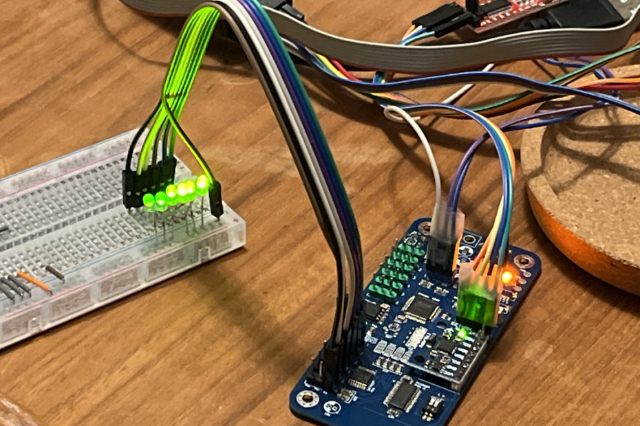
LED Test Code
For initial testing I decided to use LED lights instead of servo motors. I hooked up a string of 6 lights to the LED0 to LED5 outputs of the PCA9685. In order to do this with the Wingboard v0.1, I had modified the solder jumpers to force the MUX to select the PCA9685 output to drive the output pins instead of using default PWM input pins.
I wrote a simple function to oscillate the PWM duty cycle, and by initializing each light with different duty cycles I created a simple light wave.
Everything is working well so far. The next step is to test this with driving come servo motors and begin integrating the PCA9685 library into my Wingman project.