Notes on basic setup & testing of the JDY-40 wireless serial port module. These are simple wireless serial communication modules that work fairly well and don’t require much power to operate.
Part of the simplicity of JDY-40 is that it natively broadcasts to all other JDY-40 modules, meaning there is no additional setup required for point-to-point or one-to-many communication. This can also be used to create a hub-and-spoke type network as show in the post JDY-40 Wireless Broadcast.
There is also an upgraded module with extended range called the JDY-41. This post shows results of a JDY-41 Wireless Range Test.
Supplies
- 2x JDY-40 units (AliExpress affiliate link)
- 2x Serial to USB adapters (AliExpress affiliate link)
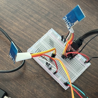
- Breadboard + Jumper wires (AliExpress affiliate link)
- Computer with PuTTY/Gnu Screen/Arduino IDE or similar serial interface
Basic Transmission Setup
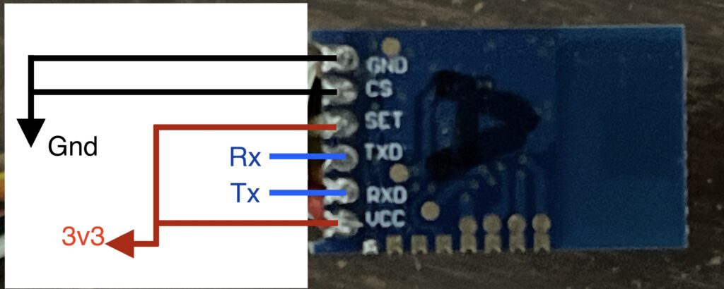
- Connect JDY-40 TX/RX to Serial adapter RX/TX
- Connect JDY-40 “CS” pin to breadboard ground rail (awake)
- Connect JDY-40 “Set” pin breadboard power rail (transmission mode)
- Connect JDY-40 “Vcc” to breadboard power rail
- Connect JDY-40 “Gnd” to breadboard ground rail
- Set Serial to USB adapters to 3.3v and connect breadboard power rail
- Connect Serial to USB ground to breadboard ground
Repeat for a second unit to communicate with.
Data Transmission
Plug the serial USB adapters into a computer (or two separate computers if you like). Open a serial tty session for each adapter. Default baud rate is 9600. For Arduino IDE or PuTTY, select the appropriate COM port (windows) or /dev/tty.* port (Mac/Linux) and baud rate.
For GNU Screen it will be something like this
> screen /dev/tty.usbserial-A50285BI 9600Whatever text is entered into one unit will be received on the other unit and sent out to the serial adapter on the other end.
Multiple Receive Units
In a configuration with three JDY-40 units, when one unit broadcasts a message it will be received by both of the other two units as long as they are all configured correctly (same RFID, DVID, and RF Channel). I only have three units to test with so I can’t confirm a higher number of units, however I see no reason why they would not be able to broadcast in a one-to-many configuration.
Configuration With AT Commands
The AT commands are used to configure the JDY-40. Start in AT mode by setting CS low and SET low. This can be used to configure or query the following settings:
- Baud rate: AT+BAUD<baud_rate_index>
- Wireless ID: AT+RFID<wireless_id>
- Device ID: AT+DVID<device_id>
- Radio Channel: AT+RFC<channel_index>
- Transmit Power: AT+POWE<transmit_power_index>
- Operation mode (CLSS Type): AT+CLSS<class_type>
Sending the command without a parameter queries the current setting. For example sending “AT+BAUD” with no parameter after will return the result “+BAUD=4” if using the default baud rate of 9600 which maps to BAUD=4.
> AT+BAUD
+BAUD=4
AT Command Line Endings
Note that the AT commands must be terminated with “/r/n”. I was unable to do this with GNU Screen on my Mac OS terminal and so I switch to using Arduino IDE for sending AT commands.
AT Mode to Transmission Mode
The JDY-40 cannot go from transmission mode to AT mode without resetting the device. However, you can start in AT mode and then go to transmission mode. This is the sequence that worked for me to go from AT mode to transmission mode.
- Start in AT mode (CS low, Set low)
- Go to sleep (CS high, Set low)
- Switch to transmission mode (CS high, Set High)
- Wake up ready to transmit (CS low, Set High)
AT Command Setup
Use the same setup as above except pull the JDY-40 “SET” pin low.
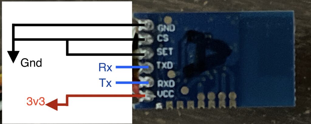
- Connect JDY-40 TX/RX to Serial adapter RX/TX
- Connect JDY-40 “CS” pin to breadboard ground rail (awake)
- Connect JDY-40 “Set” pin breadboard ground rail (AT mode)
- Connect JDY-40 “Vcc” to breadboard power rail
- Connect JDY-40 “Gnd” to breadboard ground rail
- Set Serial to USB adapters to 3.3v and connect breadboard power rail
- Connect Serial to USB ground to breadboard ground
Notes on Some of the AT Commands
Baud Rate
The JDY-40 baud rate can be set to the following options with the “AT+BAUD<baud_rate_index>”
- 1200
- 2400
- 4800
- 9600
- 14400
- 19200
For example sending the command “AT+BAUD6” which in AT mode will set the JDY-40 baud rate to 19200.
Keep in mind that when changing the baud rate of the JDY-40, it changes the baud rate of both transmission mode and AT mode. So, after changing the baud rate with an AT command the serial adapter will get an “OK” response in the current baud rate, however the baud rate of the serial adapter must be changed to match the new baud rate before sending any other AT command.
RFID and DVID
The data sheet doesn’t explain these configuration parameters much. They can each be any 16-bit integer value. I found that RFID and DVID must both match between JDY-40 units in order for transmission to be received. I’m not sure what the difference is between the two parameters, as they seem to play the same role.
Radio Channel
There are 128 different radio channel options. I don’t know what frequency ranges these channels map to. I found that the JDY-40 units did not have to be on the exact same channel in order to communicate. As long as they were within 2 or 3 channels of each other, they worked fine. Of course being on the same channel is ideal and should reduce the amount of data loss.
If you are configuring multiple links then each link should ideally be on channels with a good amount of separation (6 or more channels apart) to avoid interference between the separate links.
Transmit Power
There are 10 different transmit power options (0-9). By default the JDY-40 is set to use the highest power option. I left this at the default for all of my testing so far.
With default settings I measured the following current draw for each unit using a USB power meter. Note that this is measured at 5V before the 3.3V regulator on the serial USB adapter.
- 0.013 A @ 5V IDLE (65 mW)
- 0.016 A @ 5V Transmitting OR receiving (80mW)
Device Type
By default the JDY-40 is in transparent transmission mode, meaning that it operates as if there were a serial connection between the wireless units. The data sheet describes several other modes of operation using the 8 GPIO pins. I have not yet tested any of these other modes.
I have examined the AT command configuration you have made with the JDY-40 module. I am also trying to do it using the Arduino IDE but I cannot get any healthy response. Sometimes I get a response as empty boxes, meaningless symbols and letters and sometimes I get no response at all. Can you help?
Thank you.
Make sure you are using the default 9600 baud rate in the Arduino IDE. Also, I believe that I had line ending set to “Both NL & CR”. If it’s still not working with those settings, then I recommend trying to use GNU screen or PuTTY instead of Arduino IDE. If the problem persists with those, then it may be a problem with your hardware setup. Possibly a bad wire, loose connection, or bad USB Serial adapter. I hope you are able to get it working.
Hi Ben,
thank you for writing this up, it helped me a lot when playing with these devices.
For anyone interested, I built a USB dongle for the PC side with a 3D printed case: https://www.thingiverse.com/thing:6948523
Also, I did play a bit with the I/O pins. They work basically as expected, at least in the C4-transmitter mode. However, I found that the C0-transceiver mode with indicator LED on GPIO8 is a bit buggy, as when you push more than one button, the LED is cleared already after a single button is released and not, as I would have expected, after all buttons have been released. The I/O’s work as expected, though.
Very cool, thanks for sharing.
I’m experiencing a chronic issue with JDY-40 modules. I’ve conducted various tests using more than 10 modules and different TTL converters. I also powered the modules externally (3A continuous current), but there is excessive packet loss.
For example, when sending the “Hello” message every 2 seconds, I receive results like “ello,” “Hell,” or “Hllo” on both sides. I’ve tried adjusting the baud rate and power settings, but it didn’t help. The issue persists whether the modules are placed next to each other or 50 meters apart.
Have you encountered these issues as well?
The only time I’ve seen the JDY-40 dropping data was when the units were far apart. You might check that the Rx & Tx connections are secure. Maybe swap out jumper wires for new ones to just to see if that helps. Also, make sure that the 3.3v power supply is steady and the ground connection is solid. If you have an oscilloscope you could use it to check that the Vcc is steady over time. I only tested my units at the highest power level, so if you are running a lower power setting that could make a difference. Aside from that, double check that they are on the same radio channel. I hope one of those things helps.
Hello Ben,
Thanks for the write up. Is something like this possible :
One JDY sends a broadcast query.
All other JDY modules receive the same. The chosen one replies with the data.
If possible any chance of making a small write up on how it can be implemented.
Thanks
Thomas
Yes, I believe that is possible. That would be an interesting project. I’ll add it to my list of things to test out.
Thanks,
-Ben
Is there a way to get a notification ? A youtube channel, I could sub to perhaps.
Cheers
Thomas
I’ve been meaning to set up a mailing list to notify about new posts, but have done gotten to it yet. I’ll look into it.
Well ,I’ll keep peeking here off and on. So in case you do go ahead please leave a comment here.
Cheers
There is a checkbox for add me to mailing list, so I check on it
I just set up the mailing list recently, and it appears to be working now. It looks like your email address isn’t confirmed though. You should have gotten an email titled “Confirm your subscription to Notes To Self”. Once you confirm your email address, you should get a notification anytime a new post is published.
No , I did not get any notification. I checked my spam folder as well.
Ok, now its done.
I’m using the JDY-41 module.
I can read and write the configuration parameters keeping CS and SET low.
When I switch to trasnsparent mode (A0, CS low and SET high), same baudrate, Channel and device ID, I only get a “+Start” string back but no communcation betwee the 2 modules.
It seems like the issue is on the remote end (not the end you used to configure JDY-41 parameters). Make sure that Rx & Tx are wired up correctly on the remote end (JDY-41 Tx –> Serial Rx, and JDY-41 Rx <--- Serial Tx). You could also wire up a loopback on the remote side (JDY-41 Tx --> JDY-41 Rx) and see if everything sent from the local side is echoed back. If so then you know the JDY-41 modules are communicating.