Why does the Fourier Transform generate complex numbers in the frequency domain?
The Discrete Fourier Transform (DFT) of a signal x (lower case) generates a sequence of complex values, X (upper case). Each value of X, denoted X[k], represents how much a particular frequency, denoted fk, is part of the original signal x. The post “Discrete Fourier Transform Frequency Bins” has more detail on how to determine which frequencies are represented by each value of X.
Each DFT value, X[k], is a complex number which consists of a real part and imaginary part. However, the naming convention can be misleading because there is really nothing “imaginary” about the complex DFT values. The real and imaginary parts of each X[k] value both represent something concrete about the input signal. They encode the magnitude and phase of each component sinusoid which make up the original signal, x.
Complex numbers as pair of numbers
Rather than thinking of the DFT result as having a real part and imaginary part, you can instead think of each X[k] as an ordinary pair of numbers. So, for the complex number a + i*b, you can think of it simply as a pair of regular numbers, (a, b). This is just like a pair of numbers that can represent a point on an XY plane. For example, in the XY plane below the numbers (0.707, 0.707) represent the point shown in red.
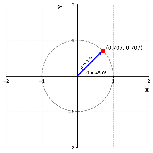
A point on an XY plane can be represented by cartesian coordinates (x, y) or polar coordinates (rho, theta) where rho is the magnitude and theta is the angle. Similarly, each X[k] from the DFT can be transformed into a magnitude and angle that tell us about the input signal.
\rho = \sqrt{x^2 + y^2} \\
\theta = \arctan\left(\frac{y}{x}\right)
The magnitude of each X[k] indicates how much a sinusoid of a frequency fk is present in the original signal, x. Similarly, the angle of each X[k] indicates the phase of the sinusoid at a frequency fk in the original signal, x.
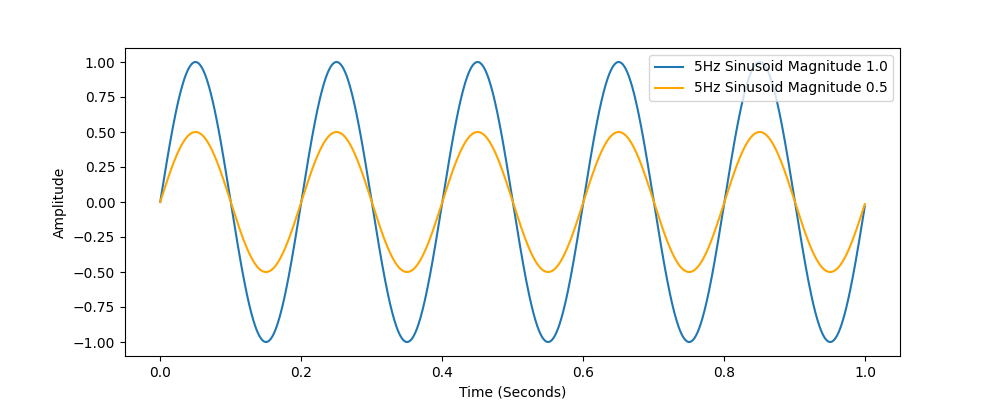
What is magnitude?
The magnitude of a sinusoid determines how big the peaks are. The blue sinusoid has a magnitude of 1.0, and the orange sinusoid has a smaller magnitude of 0.5. A sinusoid with magnitude of 0.0 would simply be a flat line.
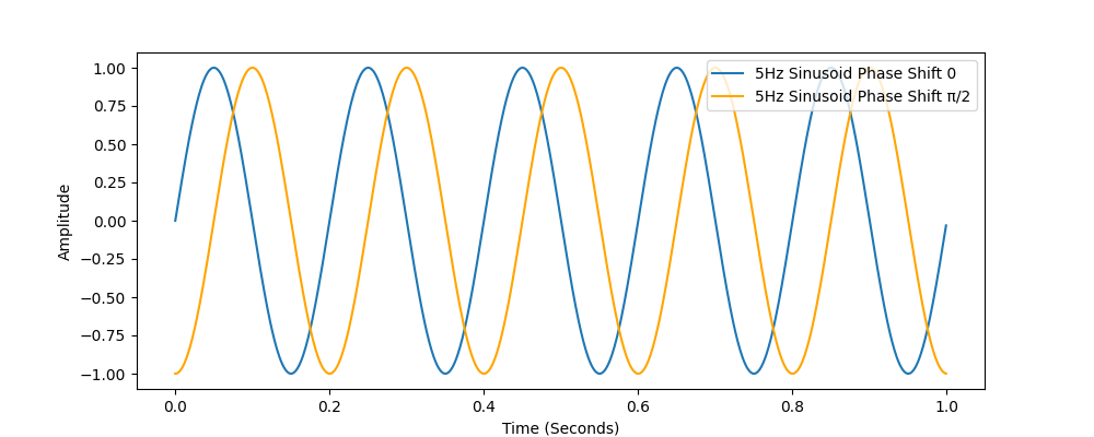
What is phase?
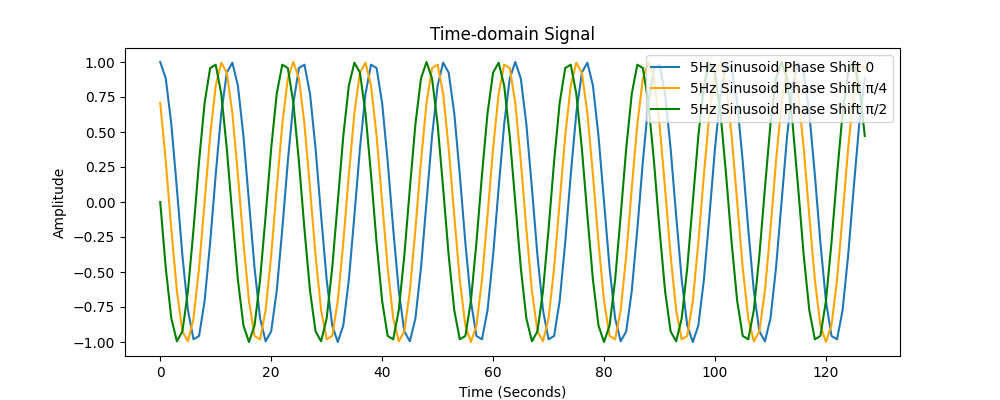
The phase of the sinusoid represents how it is shifted in time. The figure below shows a 5Hz sinusoid in blue. This sinusoid has phase shift of 0 radians (no shift). The other sinusoid is also 5Hz and is phase shifted by pi/2 radians (90 degrees or 1/4 of a full cycle).
So, when the DFT produces complex values, remember that they are just a pair of numbers that encode the magnitude and phase of the component sinusoids that made up the original signal.
Where do the two numbers come from?
Under the hood, the DFT is correlating the input signal, x, with two sinusoids of different phase shifts for each X[k]. The real part of X[k] is the correlation of the input signal, x, with a sinusoid of frequency fk. The imaginary part of X[k] is the correlation of the input signal with a sinusoid of frequency fk also, but with a phase shift of pi/2 radians (90 degrees).
This is easy to see when the DFT is expanded using Euler’s Formula.
e^{-jx} = cos(x) - j*sin(x) Starting with the standard DFT equation
X[k] = \sum_{n=0}^{N-1}x[n]e^{-j\frac{2\pi}{N}nk} \\
Substitute using Euler’s Formula where x is defined as follows
x = \frac{2\pi}{N}nkWhich gives us the following
X[k] = \sum_{n=0}^{N-1}x[n]*(cos({\frac{2\pi}{N}nk}) -j*sin({\frac{2\pi}{N}nk} ))This can be split into two separate summations like this
X[k] = \sum_{n=0}^{N-1}x[n]*cos({\frac{2\pi}{N}nk} ) - j * \sum_{n=0}^{N-1} x[n]*sin({\frac{2\pi}{N}nk})Finally, split the summations into separate two equations, each representing part of X[k]
X[k][0] = \sum_{n=0}^{N-1}x[n]*cos({\frac{2\pi}{N}nk}) \\
 X[k][1] =-\sum_{n=0}^{N-1} x[n]*sin({\frac{2\pi}{N}nk})
And there you have it. The DFT is generating two values. The first value is the correlation of the input signal with a sinusoid of frequency fk, and the other value is the correlation of the input signal with another sinusoid of frequency fk which is phase shifted pi/2 (90 degrees) from the first sinusoid. These two values are represented as a complex number.
Why correlate the signal twice for each X[k]?
Because the phase of the signal affects the DFT sinusoid correlation. If correlation were done with only one sinusoid then X[k] would be degraded by how out of phase the signal is from the sinusoid. Including a second sinusoid for each X[k] that is out phase by pi/2 radians ensures that one or both of the sinusoids will correlate with the signal when it has a matching frequency, even if the phase does not match.
To demonstrate, take the following three sinusoid signals. All of them are 5Hz sinusoids that differ only in their phase. When the DFT is run on each of them, a very different result is given.
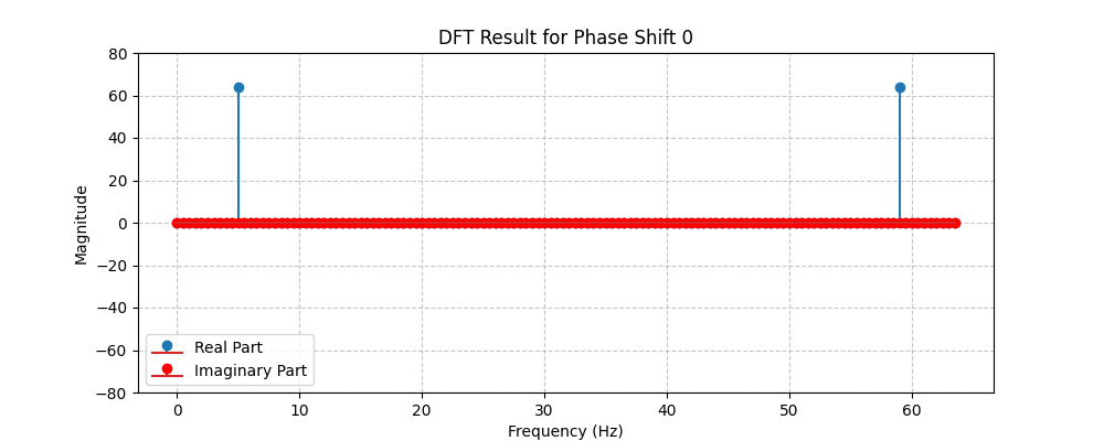
When there is no phase shift, the signal shows up in the real part of the DFT. The height of the real value spike at 5Hz is 64.
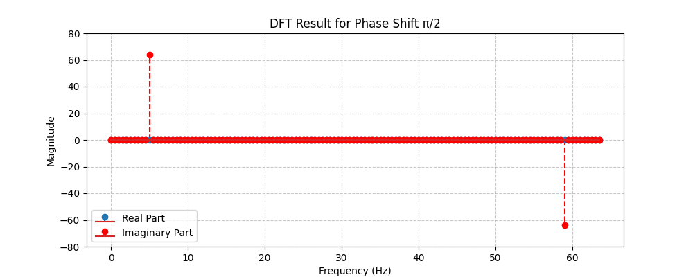
When the phase is shifted by pi/2 radians, the signal shows up in the imaginary part of the DFT, but not the real part. The height of the imaginary value spike at 5Hz is again 64.
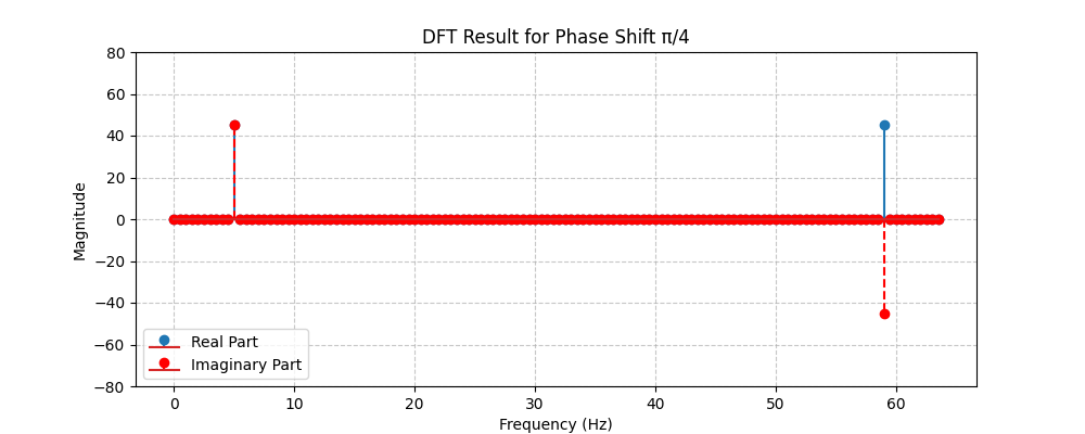
When the phase shift is at pi/4, then the signal shows up in both the real and imaginary parts, but to a lesser degree in each. The height of the real and imaginary value spikes at 5Hz are around 45.3.
The magnitude of X[k] in all three of these cases is the same, it is just being distributed differently between the real & complex part of the X[k]. This can be verified using the formula for above for rho.
\rho_{phase 0} = \sqrt{64^2+ 0^2} = 64 \\
\rho_{phase \frac{\pi}{2}} = \sqrt{0^2+ 64^2} = 64 \\
\rho_{phase \frac{\pi}{4}} = \sqrt{45.3^2+ 45.3^2} = 64
This is why it is necessary for the DFT to correlate the input signal against two sinusoids for each X[k].
The phase can also be extracted from these X[k] values using the formulas for theta.
\theta_{phase 0} = atan(\frac{0}{64}) = 0 \\
\text{} \\
\theta_{phase \frac{\pi}{2}} = atan(\frac{64}{0}) = \frac{\pi}{2} \\
\text{} \\
\theta_{phase \frac{\pi}{4}} = atan(\frac{45.3}{45.3}) = \frac{\pi}{4}