Here are the equations for the DFT & the frequency of each bin, fk.
Discrete Fourier Transform
X[k] = \sum_{n=0}^{N-1}x[n]e^{-j\frac{2\pi}{N}nk} Bin Frequencies
\text{ \underline{For k = 0...N/2}} \\
f_k = k * f_s / N
\text{ \underline{For k > N/2}} \\
f_k = f_{(N-k)}f_s \text{: The sample frequency (Hz)} \\
N \text{: The FFT size} \\
f_k \text{: The frequency (Hz) of FFT bin } kIntuition for the Equations
DFT Overview
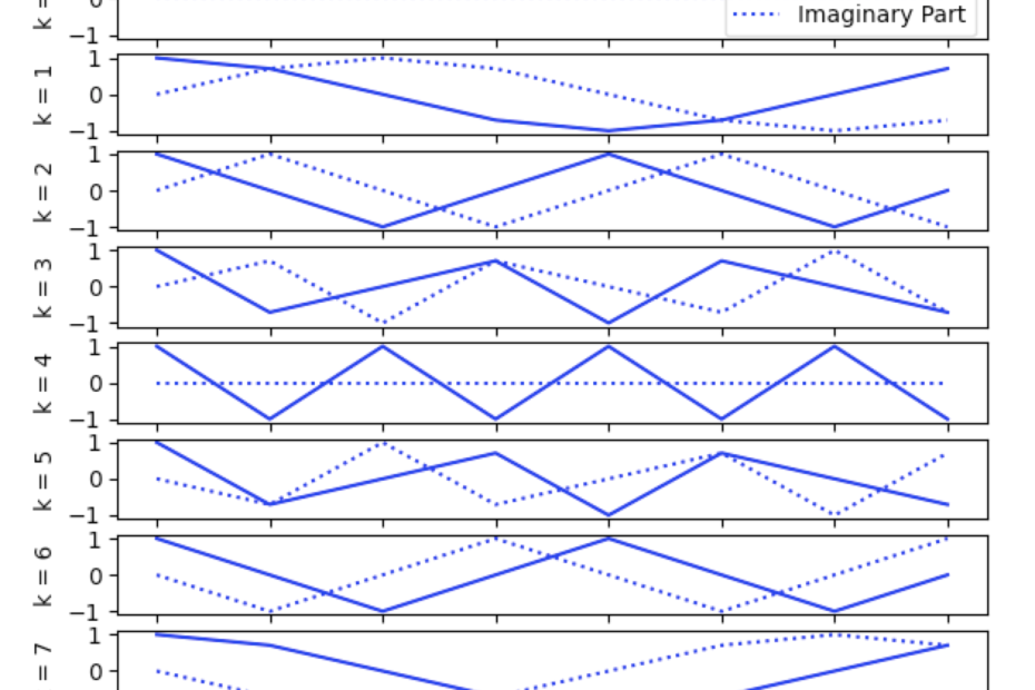
The Discrete Fourier Transform (DFT) takes an input signal, x[n] and produces an array of values, X[k]. Each value in X[k] represents how much of the original signal is composed of a particular frequency, fk. The example below uses an 8-point DFT and so it used 8 complex sinusoids (f0 to f7) and produces the output series X[k] with 8 complex values (X[0] to X[7]). For more on why these values are complex checkout the post, Why Are Complex Numbers in the Discrete Fourier Transform?

Each value of X[k] tells you how much of the frequency fk is in the original signal. The first bin where k=0 is kind of a special case because the frequency f0 = 0 and so X[k=0] is actually just the sum of all the input signal values.
The real part of each complex sinusoid is shown as a solid blue line, and the imaginary part is shown as a dashed blue line. The values of X[k] are also complex valued, though often only the magnitude is used.
Deriving The Frequency Bin Equations
For k ≥ 1 each basis vector is a sinusoid of different frequencies. The basis vector for k=1 is the lowest frequency. This is a sinusoid where one period takes N samples. Knowing this we can write the equation for the period, T.
T_{k=1} = NSince the frequency is the inverse of the period, we can calculate the frequency like this:
f_{k=1} = 1/T_{k=1} = 1/NFor k = 2 the sinusoid goes through two cycles, so the period is this:
T_{k=2} = N/2And again, the frequency is the inverse of the period like this:
f_{k=2} = 1/T_{k=2} = 2/NFor k = 3 the basis vector sinusoid goes through 3 cycles. Now we can see a pattern in the frequencies and can make a generalize equation for each bin, k
T_k = N/k
f_k = 1/T_k = N/k
These equations hold for 0 < k <= N/2
For k > N/2
Beyond k = N/2, the sinusoid frequencies mirror the K < N/2 frequencies. You can see in the image above that the real part of the sinusoid for k=3 is the same as k=5. The imaginary part of the sinusoids are phase shifted but the frequency is also the same. These are sometimes called the negative frequencies and are complex conjugate to the k = 1 to k = N/2 frequencies.
So, for k > N/2
f_k = f_{N-k} \text{ for k > N/2}If the input signal contains only real values then the values of X[k] are also mirrored. That means that in practice, when processing real valued inputs, the values for k > N/2 are redundant information.
Sample Frequency
The unit for fk in the equations above is in cycles/sample. When processing real world signals with the DFT we usually sample signals in time and want to produce frequency analysis in Hertz (Hz) which is cycles/second. In order to use the above equations for real world signals we also need account for the sample frequency, fs, which is in samples/second
f_k \text{(in cycles/second)} = f_k \text{(in cycles/sample}) * f_s \text{(in samples/second)} = (N/k) * f_sNote About DFT Shifting
Often the values of the DFT result for k > N/2 are shifted so that the whole output array is centered around the zero frequency value. If this shift is done, the the values calculated with the equations above also need to be shifted to match up. Some FFT libraries will shift the values internally while others do not. Make sure you know what the software library is actually giving you.