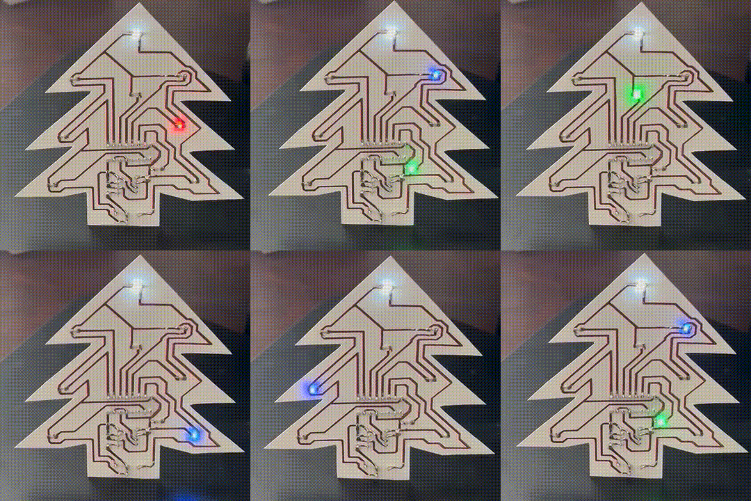
This Christmas-themed paper circuit uses no microcontroller, only a 555 timer and CD4017 decade counter to drive blinking LEDs. The KiCad project and other files can be found in the github repo.
This circuit was made using a craft cutting machine to cut copper traces from adhesive copper sheets, similar to this project. I found that thick copper traces and wider space between traces is easier for the cutter to manage without messing up the copper foil. So, I decided to use DIP package ICs to accommodate the thicker traces and allow for more spacing between them.
Materials
- NE555 Timer (DIP-8 package) (AliExpress affiliate link)
- CD4017 IC (DIP-16 package) (AliExpress affiliate link)
- SMD resistors (2k7 and 5k1), capacitors (10u and 0.1u), and LED lights (0805 package) (AliExpress affiliate link)
- Vertical CR3202 battery holder (AliExpress affiliate link)
- Adhesive Copper sheets
- Transfer Tape
- Craft cutting machine (Ex: Silhouette Cameo 4)
- Soldering supplies
Schematic
Schematic and Layout were done with KiCad 7. The design has three main parts:
- Power
- Clock
- Counter + LEDs
The clock is an NE555 timer IC driving a square wave. The counter takes the clock as input and toggles the output pins one at a time causing the LEDs to blink on and off.

Layout
The battery at the bottom doubles as a stand for the tree. The ICs are placed on the back so that the IC legs will poke through to the side with copper. I had planned to use 3mm LEDs originally but switched to 0805 & 1206 SMD LEDs instead. This worked out because the copper pads are very similar.

Function was my main focus, but I also managed to lay down the traces into the general shape of a Christmas tree. I first sketched out the shape using the User.1 layer and then used it as a rough guide for layout.
In order to make the traces easier to cut out, I used a minimum of 1mm trace width as well as 1mm space between traces. To set these as constraints the Kicad PCB Editor you go to “File” -> “Board Setup” -> “Design Rules” -> “Constraints”

Export Copper Layer Image
The traces can be exported to an image file by going to “File” -> “Print”. Select only the front copper layer called F.Cu. Then print to PDF and convert to PNG with 300dpi resolution. On Mac OS you can select “Open in Preview” where it can be exported as a PNG.


The resulting PNG image shows where the copper needs to be in the final circuit.

Cut Out Copper Traces
In Silhouette Studio, start with a new project. Open the copper trace image with “File” -> “Open” and select the copper trace image.
Next, trace the image by doing the following:
- Select the Trace Menu (butterfly image) on the right menu bar
- Click “Select Trace Area” and select the area around the copper trace image
- Select “Outline”
- Select “Trace Outer Edge” under “Trace Style”
- Note that the “Trace Outer Edge” option will not cutout the through-hole vias. If you want the vias cut, the use the “Trace” option.
At this point the traces should be outlined in red, indicating the path where the craft cutter machine will cut.

With the red traces in place, it’s time to click on the “Send” tab at the top of Silhouette Studio. Connect the cutting machine, and select “Cut” under “Carriage 1”. I used the following settings:
- Number of passes: 1
- Force: 2 or 3
- Speed: 1
The result should look something like this

Then put the copper on some transfer tape and peal away the extra copper with tweezers. This part is tedious but also very satisfying.


Transfer to the final substrate. I transferred mine to card stock paper. It is important to press the copper down down well before removing the transfer tape. A guitar pick or spudger tool works well for this.


Solder Components
I think it’s best to start with the through-hole components (NE555, CB1047, & Battery holder), using tweezers to poke holes where the IC pins need to go. Adding extra solder on the through-hole joints helps ensure that there is a good connection to the copper traces.
The very top LED is tied directly to the battery and will stay illuminated continuously. The rest of the LEDs will be blinked on and off one at a time.


There is a pause in the pattern of lights since this design only uses 8 out of the 10 outputs of the counter. This leaves the design open to adding two more LEDs to the pattern. To remove the pause but still only use 8 LEDs, the CD4017 counter output 9 could be hooked up to the reset pin causing the counter to skip 9 & 10. I like the pause, though so I just left outputs 9 & 10 unused.
