This light box is illuminated by individually addressable LED strips and controlled over Wifi.
The code and scenery template pdf can be found here: https://github.com/benjohnemmett/LightBox/
The 3D printed insert file can be found here as an stl or obj: https://www.tinkercad.com/things/ihSa8Sw1An6-light-box-insert-rev-2
Supplies
- Wooden box: Mine is from Hobby lobby and has a glass front (https://www.hobbylobby.com/crafts-hobbies/wood-crafts-blank-surfaces/frames/square-wood-shadow-box/p/80811310)
- WS2812 LED Strip: Closely spaced lights work best. Mine fit 22 lights per row. (https://www.amazon.com/gp/product/B09PBGZMNS)
- WeMos D1 Mini module. (AliExpress affiliate link)
- 3D Printer + filament: I used green PLA at the time. A lighter color would look better though.
- Thin wires (around 24 AWG) & soldering tools
- Paper for making the scenery
Assembly
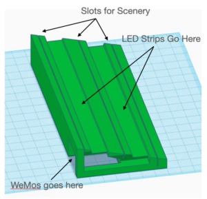
Print the Insert
The standard PLA print settings on any slicer should be fine. I used 0.3 mm layer height and 10% infill and sliced with Cura. The filament type & color are not important, though lighter colors will reflect light the best. I would have used white PLA but all I had available at the time was green.
The insert is designed to fit my box which has inner dimensions of 168mm x 70mm. The design can be tweaked in TinkerCAD if adjustments are needed for other box sizes.

Prepare the LED Strips
Measure out and cut two LED strips to fit the insert. Fit as many lights in each row as you can to maximize the amount of light in the box. Cut on one of the lines between the lights. Be sure to leave the copper pads are where wires will be soldered on.


Solder on wires to the end of each LED strip. I used 24 AWG wire from ethernet cable scrap. These can carry up to 577mA which is well above the ~180mA that I measured. There are three solder pads for Ground, Data, and +5V power. In my LED strip data is in the center with ground above, and +5V power below. There should be pad markings on near the beginning of the LED strip.
Solder the data wires for each strip to D1 & D4 pins on the WeMos board or on the perf board. It is also helpful to solder a jumper to pin D3 which needs to be grounded each time you reprogram the board. Also solder the +5V wires to the 5V WeMos pin and the Ground wires to the WeMos GND pin.
I soldered the wires to a perfboard shield, but they can be soldered directly to the WeMos module.

Program the WeMos
Pull the Arduino code from the Github repo. Change the wifi name & password in “LightBox_Wemos.ino”. Update the pin numbers if necessary. Update the LED count to match your setup.
#ifndef STASSID
#define STASSID "wifi-name"
#define STAPSK  "wifi-password"
#endif

/////////////////////////////////////////////
// LED Stuff
/////////////////////////////////////////////
#define FRONT_LED_PIN   D4
#define BACK_LED_PIN    D1
#define LED_COUNT       22
Put the Wemos in program mode and by grounding pin D3, and upload the code from Arduino IDE. More information on Wemos D1 Mini Programming can be found here.
Install the WeMos & lights
Thread the lights up through the spot for the WeMos and put the WeMos in place. The lights need to bend around to the top of the insert. If the lights have adhesive on the bottom, it can be used to stick them down. Otherwise, hot glue or double-sided tape will also do the trick. I also used a bit of hot glue to hold the WeMos in place.


The USB port should be facing outward to allow for powering the Light Box. It can also be used for firmware updates. To do firmware updates which the WeMos is installed in the insert is a bit tricker. I made a little jumper tool to help put the board in program mode. I would recommend leaving a jumper wire or installing a button to pull D3 low if you plan to do firmware updates often.

Test the Web Controls
The light box hostname is “lightbox” so you may be able to navigate to http://lightbox.local. This would not work on my router. If that is the case, you can get the IP address by opening the serial monitor in Arduino IDE and hitting the reset button on the WeMos. When the Wemos starts up and connects to Wifi, it will print IP address that the Lightbox has been given.
The controls at the time of this post are pretty basic. You can set the red, green, & blue values of each light as well as a pulse rate. Setting pulse rate to zero (all the way to the left side) disables the pulse. Just hit the “Update” button to push settings to the LightBox.

Create Some Scenery
Create up to five layers of scenery. They can go in the three slots of the insert as well as in front and behind the insert. I put the smallest piece shown in front of the insert and the other two pieces in the first two slots. I created these scenery pieces as a proof of concept for the light box. Now that I have it all working I would like to use a craft cutting machine to do some more detailed and higher quality designs. That’s a whole new project though.


The Github repo includes a pdf to use for figuring out the size of the scenery. The pdf shows the minimum height of each scenery layer. This image shows the minimum size template layers in the LightBox.

Conclusion
This is a basic start to a project that can go in different directions. I look forward to creating different scenes, trying out different color lighting combinations, and updating the code for new lighting effects.
