As part of a flight controller project, I wrote some code to capture servo control pulse width modulated signals from an RC plane receiver with a ATmega4809. The initial tests show good performance and reasonable accuracy.
Source Code Repo: https://github.com/benjohnemmett/Wingman
Tag for this commit: https://github.com/benjohnemmett/Wingman/releases/tag/pwm_input_capture
Design
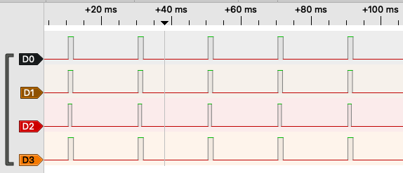
The objective is to capture 4 PWM channels which each run at 50Hz and have a pulse width from 1 to 2 milliseconds. These signals typically control some servos and an ESC on the RC plane.
The design takes advantage of the four type B hardware timers in the ATmega4809. There are four input capture pins with pin change interrupts that handle restarting each the timer on a rising edge and reading each timer value on a falling edge.
The timer value is converted to seconds like so:
Pulse Width = TimerTicks * \frac{ClockDivider}{F_{cpu}}The type B timers only have clock divider options of Fcpu or Fcpu/2. They can also use the clock rate from the type A timer which provides more options (1/2, 1/4, 1/8, 1/16, 1/64, 1/256, 1/1024). I decided have each type B clock use clock divider of 2. At 20MHz CPU clock frequency this gives a resolution of 0.1 microseconds per timer tick and a max measurable range of 6553.6 microseconds before the counter rolls over. This is a good amount of timer resolution, and that range exceeds the minimum requirement of 2000 microseconds with plenty of margin.
The pulse width values are converted to microseconds and stored as uint16 values. In an 8-bit MCU like this one, care should be taken to access these 16-bit values atomically to avoid reading one byte before an update and the other byte after.
Dumb ISR Luck
After successfully testing each channel individually, I found that measuring all four channels simultaneously gave bad results for all but channel 1. When I unplugged channel 1 from the MCU, I got a good value for channel 2 and bad values for channels 3 & 4. It appeared that the ISR logic for handling a channel somehow corrupted the logic for the channels handled afterward.
Not seeing an obvious reason for this, I decided to modify the code so that instead of clearing each interrupt flag individually as it processes a single channel, it stores the interrupt flag values and clears the flags at the start of the ISR. I’m not sure exactly why, but this appears to have resolved the issue and now the MCU measures accurate pulse widths on all 4 channels simultaneously. It’s possible that I just wasn’t clearing the interrupts correctly before.
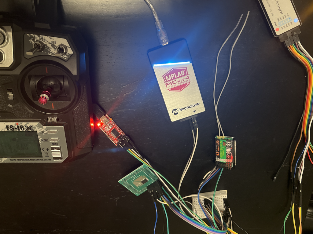
Test Setup
The ATmega4809 is on a break out board connected to channels 1-4 of an FS-iA6 receiver. A USB logic analyzer is capturing signals from the receiver to evaluate accuracy of the input capture program on the ATmega4809. The FTDI serial to USB converter captures UART0 output which is printing measurement values.
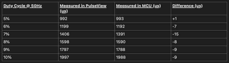
Test Results
The test results show the input capture program to be fairly accurate. The measurements tend to be smaller than the actual pulse width by no more than ~2%. Initial tests show that the error bias could be dependent on the pulse width. The level of error is negligible for my application, though I would like to do more tests to understand better what is causing it.
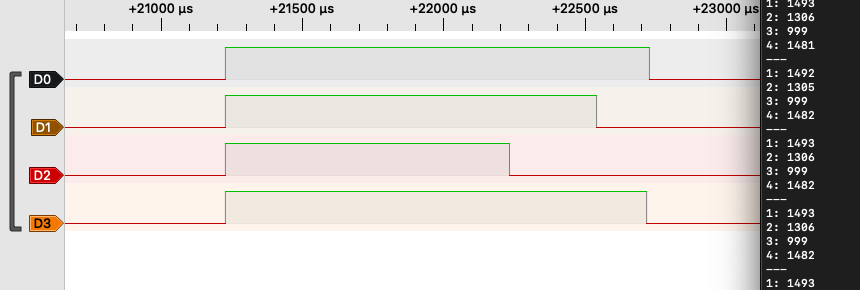
The test data capture shown above was done while leaving the transmitter control sticks for the servos (channels 1, 2 & 4) in neutral positions with throttle (channel 3) which was all the way down. The differences in pulse width in the servo channels shown above are due to trim adjustments in the transmitter. I also monitored the measured values as the control sticks were moved around and found that the measurements to be reasonably accurate.
Potential Improvements
This design is a means of getting to a working solution in a quick and simple way. Here are a few notes on potential improvements that could be made.
- Reduce ISR processing time by putting each input pin on a separate PORT so that they would have separate interrupt service routines. This would avoid needing logic in the ISR to check which pin changed.
- Free up some timers by sharing a single timer with multiple input pins. This could be done by alternating between input pins and skipping some pulses. A single timer could handle two inputs for a reduced update rate of 25Hz (missing every other update per channel). Or similarly one timer could handle all four inputs with an update rate of 12.5Hz.
- Get immediate counter value capture by using the Event System with the Input Capture Pulse-Width Measurement mode. This stores the counter value to special registers when an event occurs (like a pin change). So even if the interrupt is not handled immediately, the correct timer value is already stored. This is probably the best overall improvement.