I set out to make a custom PCB for one of those games with a circle of lights where the player tries to hit a button to stop a light at just the right time. In the end, I took it a step further and wrote the firmware to support multiple operating modes.
Repo: https://github.com/benjohnemmett/CircleOfLight
Hardware Schematic Design
The main requirements I had for this design are:
- Use an MCU that I already have (due to chip shortage)
- Include 12 or so LED lights in a circle pattern
- Include 1 or more push buttons for user interaction
- Run on 3V to 5V battery power
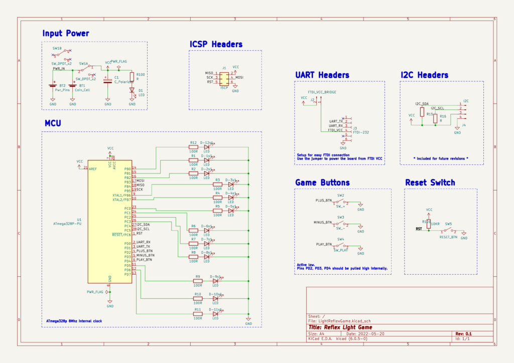
I went with the ATMega328P MCU since I have a few extras. This has plenty of GPIO pins to drive 12 LEDs, plus 3 pins for input buttons. I also decided to throw in UART and I2C headers because I still had pins left over and it will allow for adding more features later on. The coin cell battery was chosen because I had some spare batteries & holders and it meets the voltage requirement. The rated 220mA from a CR2032 coin cell should be enough to drive the MCU (max 12mA @8 MHz) and most of the lights (~20mA each) simultaneously. I also added Vin headers to leave other power options open.
Here is the schematic in Kicad.
PCB Layout
The idea was to make the PCB usable as a handheld game with buttons in the lower corners and the display in the top center. I made a reference circle on the user.1 layer to help me get the LED lights laid out. The MCU fits well in the lower center where it will not interfere with the user controls. Most of the components are placed on the front. The back side is only for the battery holder, power switch, and reset button.
For routing traces, I put most of them on the front and only went to the back layer when absolutely necessary. Looking back, I’m not sure why I didn’t use a ground plane on the back.
I also added a mounting hole at the top which could be used to put the game on a keychain or lanyard.

Firmware
The main objective was to program a game of reflexes, where the player presses and holds the play button (right side) and the light begins circling around. The player then lets go of the play button and the light stops. Point values are given (or taken away) based on which light the player stops on. The plus/minus buttons (left side) could also be used to speed up/slow down the game which also increases/decreases the point values. After three rounds, the total is tallied and reported to the user by blinking certain lights.
I ended up making the Reflex Game plus two more programs that can run on this hardware, Countdown Timer & Hardware Test. I also wrote a main menu program that runs at startup and allows the user to pick which program to run. The first three lights (12 o’clock, 1 o’clock, and 2 o’clock) correspond to the three programs. The plus & minus buttons can be used to select a program, and the play button initiates it. Only three programs are implemented now, but there is a possibility to include up to nine more programs on the main menu. To exit a program, the user holds the minus button for 2 seconds and is returned to the main menu.
Final Build and Test
Here is a short demo of turning on, selecting the Reflex Game from the menu, playing a quick game, and seeing the score blinked out. Since I turned up the speed to the highest, every score is multiplied by 5x.
Retrospective
This was a fun build and a good step forward for me in embedded systems design. Looking back on it only a short while later I already see that my PCB layout could have been much better, but for something this simple, it worked out fine.
I am pretty happy with how the firmware ended up and I’d like to come back to it later and see what other programs I could add to the other nine slots.
This project definitely has its limitations and imperfections. Here are a some things I might update if I pick this up later.
- Make the main.cpp update loop based on a timer instead of _delay_ms(1) for a more accurate & consistent update loop.
- Make the update loop period configurable by the program.
- Allow for multitasking
- Ex: Start a countdown timer in the back ground and then run another program until the timer expires.
- Use higher resistor values for the LEDS.
- 100 ohms leaves them very bright and drains the battery quickly.
- Illuminating more than a few lights simultaneously causes MCU brown out.
- Design a 3D printable enclosure for the game