Overview
The Adafruit MCP2221 breakout board can be used to bridge I2C to USB. I was able to read & write data on a 24LC256 EEPROM chip using I2C by driving the MCP2221 from my laptop with python. This handy module seems like a great way to test out I2C devices interactively.
My Setup
- Adafruit MCP2221 breakout board https://www.adafruit.com/product/4471
- STEMMA QT to male headers (optional) https://www.adafruit.com/product/4209
- 24LC256 256-Kbit I2C Serial EEPROM https://www.microchip.com/en-us/product/24LC256
- Python version 3.9.2 running on Mac OS with
- Required libraries: hid, adafruit-blinka
Python Setup
I setup a new virtual environment and installed the adafruit-blinka & hidapi libraries. Adafruit has setup instructions for Linux & Windows as well here https://learn.adafruit.com/circuitpython-libraries-on-any-computer-with-mcp2221/setup. I did not use anaconda and I’m not running a jupyter notebook for this.
FlyerII:MCP2221 ben$ python -m venv ~/.virtualenvs/adafruit
FlyerII:MCP2221 ben$ source ~/.virtualenvs/adafruit/bin/activate
(adafruit) FlyerII:MCP2221 ben$
(adafruit) FlyerII:MCP2221 ben$ pip install hidapi adafruit-blinka
Collecting hidapi

...

Successfully installed Adafruit-PlatformDetect-3.19.3 Adafruit-PureIO-1.1.9 adafruit-blinka-6.20.1 hidapi-0.11.0.post2 pyftdi-0.53.3 pyserial-3.5 pyusb-1.2.1
Set the BLINKA_MCP222 environment variable.
(adafruit) FlyerII:MCP2221 ben$ export BLINKA_MCP2221=1Hardware Setup
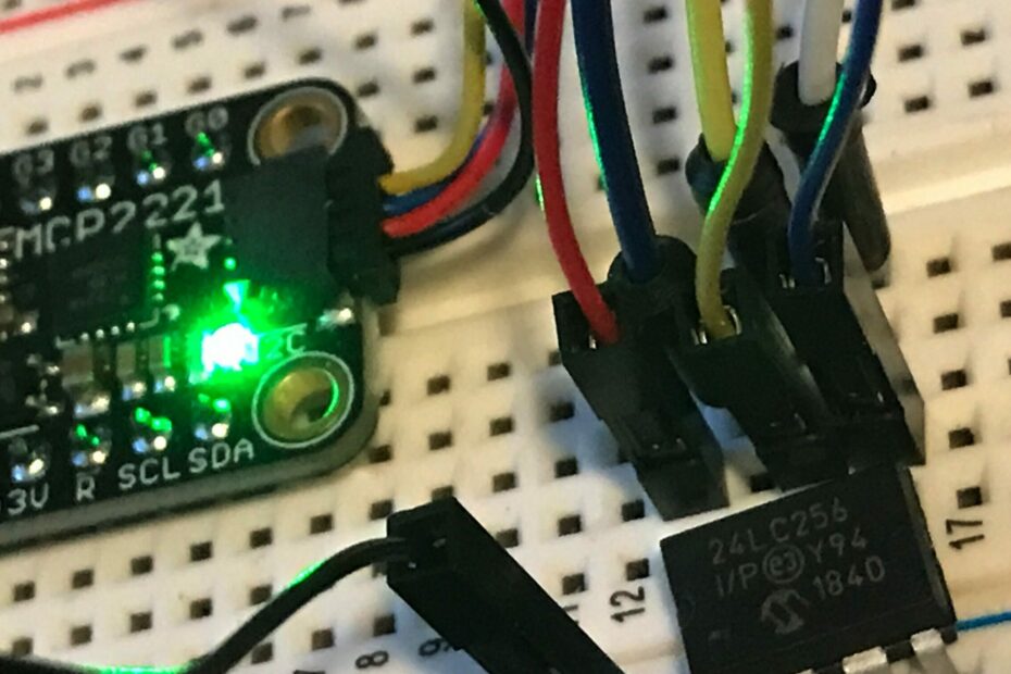
I used the STEMMA QT to male header adapter which has 4 wires, red (5V), black (GND), blue (SDA), yellow (SCL). The 24LC256 accepts Vcc of 1.7- 5.5V, so I use the 5V coming from the MCP2221. The Vss pin is tied to ground. The address pins (A0, A1, A2) determine the device I2C address. I tied the address pins all to ground making the address 0x50. Then I connected the SDA (blue) & SCL (yellow) header pins to chip pins 5 (SDA) & 6 (SCL). Finally I tied the WP (write protect) pin to ground to enable writing.


After wiring it up I plugged the USB cable from the MCP2221 to my laptop.
I2C from Python
In python I imported the board library and checked to see if the EEPROM is connected.
>>> import board
>>> iic = board.I2C()
>>> iic.scan()
[80]
The scan found my device with address 0x50 (80 in decimal).
At this time I also hooked up a logic analyzer and startup up PulseView to capture traffic. I’m not going over logic analyzer details in this post though.
Reading & Writing
After quite a bit of data sheet reading, logic capture examining, and fiddling with the board.I2C class I was able to read & write the EEPROM with the following commands.
Writing
I wrote the value 0x0B to the address 0x0000 (high byte transferred first) with the following command.
>>> iic.writeto(0x50, bytearray([0x0, 0x0, 0x0B]))And here is the logic capture.

Reading
I read the same address back to verify that 0x0B was written to it with the following.
>>> b_in = bytearray(2)
>>> iic.writeto_then_readfrom(0x50, bytearray([0x0, 0x0]), b_in, in_start=1, in_end=2)
>>> b_in
bytearray(b'\x00\x0b')
Here is the logic capture for that. Setting the read address and then getting the value happens about 10 ms apart.


Conclusion
It took a bit of fiddling around to figure out the optional arguments in the board.I2C python class. I’m still not sure why the writeto_then_readfrom() method needed a 2-byte array and populated the first byte with a zero. The logic captures look good though.