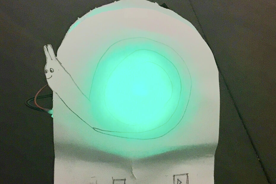
I made a countdown timer using a string of WS2818 LED lights coiled in a spiral pattern which is driven by an ATMega328p.
Source code and hardware files available here: https://github.com/benjohnemmett/Snail-Timer
User Interface
The controls are simple. The Snail Light has three buttons: minus, plus, & start/stop. Before starting the timer, the plus & minus buttons are used to set the countdown time in 1 minute increments with a max of 30 minutes. The start/stop button is used to start the timer. While the timer is counting down, the plus & minus buttons are not used.
Hardware Layout
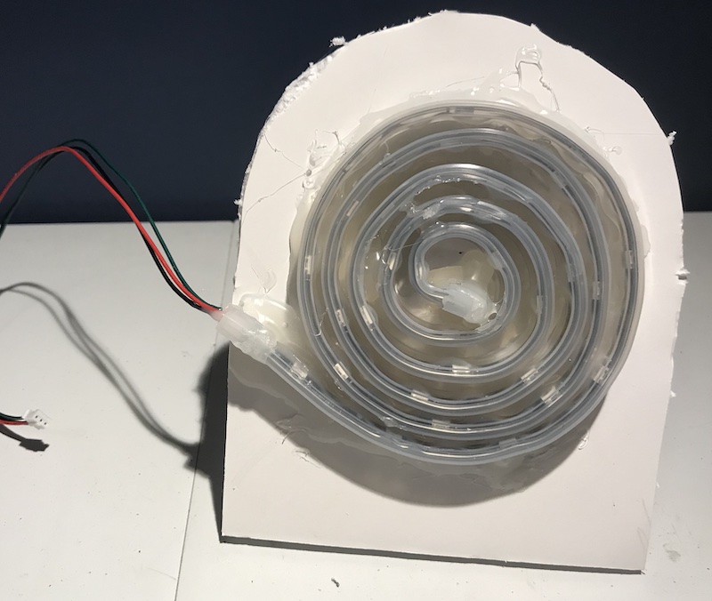
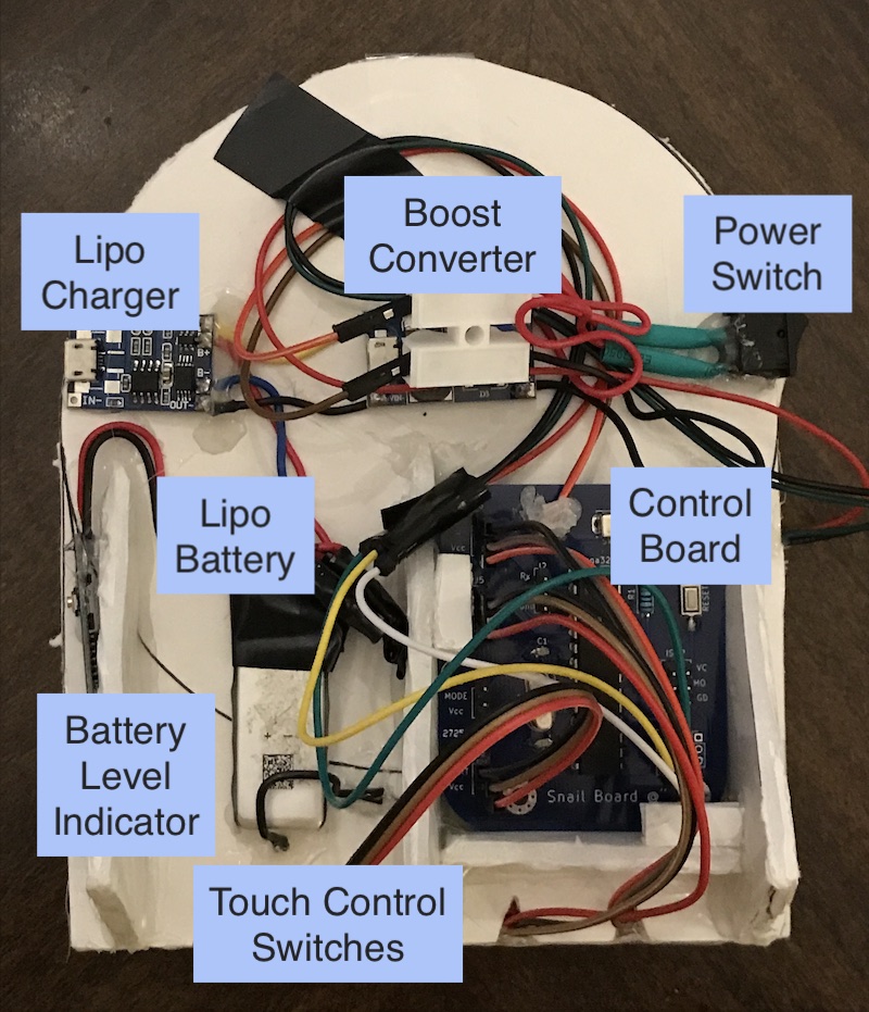
- Lights – Adafruit NeoPixel LED Strip
- LiPo Charger – TP4056 Lithium Battery Charger Module
- Boost Converter – MT3608 with Micro USB
- Touch Control Switches – TTP223 Capacitive Touch Switches from AliExpress
- LiPo Battery – 300 mAh 3.7v lipo
- LiPo Level Indicator – 1S 3.7v module from AliExpress
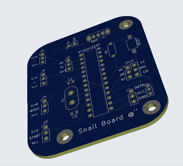
Control Board
I created a control board in Kicad which breaks out the following
- GPIO pins for the four control buttons
- LED strip data, power, & ground
- Reset button
- Power switch
- Crystal oscillator
- ICSP header pins
- UART pins
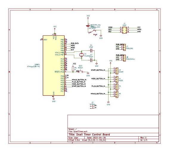
Not all of these elements are used in the first version of the timer but putting them in opens up the possibility of adding features without ordering new boards. The kicad project files are included in the github repo.
I ordered the minimum five boards from JLCPBC. The price was reasonable and although it took a while to get them here, I’m happy with the quality of the boards.
Retrospective
If I were to build Snail Timer version 2 here are a few things I would consider.
- Use a crystal oscillator for improved time accuracy
- Replace plus & minus buttons with a dial (pot/rotary encoder) to set the time
- Add sound when time is up and for user interaction
- Create an enclosure
- Allow for setting custom light colors