My son was in need of game buzzers on short notice. So I put together something quick & simple that got the job done. This has 5 buzzers connected to an Arduino Nano, which could support up to 8 buzzers. When a player presses their button, it lights up and the buzzer sounds. Only one buzzer lights up at a time, so you know who buzzed in first.
Project Supplies
- Arduino Nano (AliExpress Affiliate https://s.click.aliexpress.com/e/_ollcyj3)
- Multicolored momentary push buttons with LED (Amazon https://a.co/d/aVIzLaP)
- Active Buzzer (AliExpress Affiliate https://s.click.aliexpress.com/e/_oDR8Bln)
- Plenty of wire (AliExpress Affiliate https://s.click.aliexpress.com/e/_omgcEHb)
- Perfboard (AliExpress Affiliate https://s.click.aliexpress.com/e/_okbkNm9)
- Female header pins (optional)
- Soldering equipment
An Arduino Uno board or any Arduino board with enough digital GPIO pins could also work for this project. It requires two GPIO pins per buzzer.
I mounted the Arduino Nano to female headers on the perfboard to allow removing the Arduino Nano easily. However, the Arduino Nano could also be soldered directly to the perfboard.
Hardware Assembly
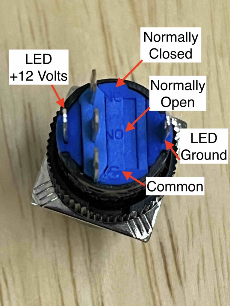
The five LED buttons are rated for 12 volts, but can light up bright enough with only 5 volts. Each light has 5 pins on the bottom. I connected both the LED ground and the Common pin to ground. The Normally Open (NO) pin and the LED 12 Volt pins each get connected to the Arduino GPIO pins.
Each buzzer requires 3 wires to connect to the Arduino: LED power, button (NO), and Ground. I used the following wire color convention.
- Ground wire – Brown
- Button wire – Yellow
- LED wire – Red
The brown ground wires connect to each Common pin and LED Ground pin on the buttons, and all come together at the Arduino ground (GND) pin.
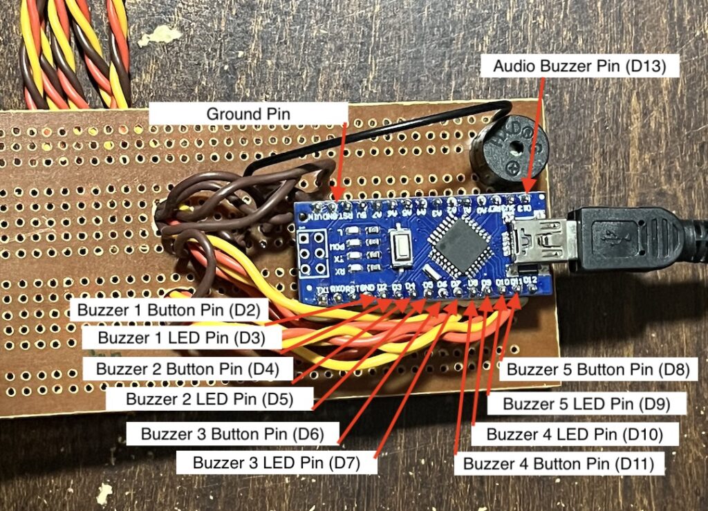
The yellow wires connect each button’s Normally Open (NO) connector and then to their own Buzzer Button pin on the Arduino. For buzzer number 1, the yellow wire connects to the Arduino D2 pin. For buzzer number 2, the yellow wire connects to the Arduino D4 pin, and so on.
The red wires connect each button’s 12V pin to it’s own Arduino Buzzer LED pin. For buzzer number 1, the yellow wire connects to Arduino D3 pin. For buzzer number 2, the yellow wire connects to Arduino D5 pin.
I drilled 1/4 inch holes in the perfboard and ran all wires through it for strain relief.
The audio buzzer element, which actually makes the buzzer sound is connected to Arduino pin D13 and to ground. The black jumper wire connects the buzzer to ground.
The project can be both powered and programmed over the Arduino Nano USB port. Once the Arduino is programmed, it can be powered by any USB power supply.
The handle of each buzzer button is just thin cardboard rolled into a tube with the button on one end and the wires running through it. It is not shown, but where the wires are soldered to the button, they are wrapped in electrical tape to prevent shorting and provide strain relief.
Arduino Code
The code below goes on the Arduino Nano and is fairly simple. On startup, it illuminates each LED sequentially briefly sounding the buzzer each time a new light is illuminated. It also sets each LED pin as an output and each button pin as an input with the internal pullup resister enabled. Note that the buttons are low asserted. It also has some logic to disable the buzzer sound if any button is held down on startup.
In the main loop, the code polls each button input pin to see if a button is pressed. When a button is pressed, the code sounds the buzzer and blinks the LED. It holds the LED on for three seconds (3000 ms) in order to make it clear which button was pressed. Once a button has been pressed, the processor will not check for other button presses again until the LED is turned off again.
#define NUMBER_OF_BUZZERS 5
#define NUMBER_OF_LED_BLINKS 3
#define LED_HOLD_TIME 3000

const int buttonPins[NUMBER_OF_BUZZERS] = {2, 4, 6, 8, 10};
const int ledPins[NUMBER_OF_BUZZERS] = {3, 5, 7, 9, 11};
const int buzzerPin = 13;
bool enable_buzzers = true;

void setup() {

  pinMode(buzzerPin, OUTPUT);

  for (int i = 0; i < NUMBER_OF_BUZZERS; i++) {
    pinMode(ledPins[i], OUTPUT);
    pinMode(buttonPins[i], INPUT_PULLUP);

    if (digitalRead(buttonPins[i]) == LOW) {
      enable_buzzers = false;
    }
  }

  for (int i = 0; i < NUMBER_OF_BUZZERS; i++) {

    digitalWrite(ledPins[i], HIGH);

    if (enable_buzzers) {
      digitalWrite(buzzerPin, HIGH);
    }
    delay(200);
    digitalWrite(buzzerPin, LOW);

    delay(300);
    digitalWrite(ledPins[i], LOW);
  }
}

void loop() {

  for (int i = 0; i < NUMBER_OF_BUZZERS; i++) {
    int button_state = digitalRead(buttonPins[i]);
    if (button_state == LOW) {

      if (enable_buzzers) {
        digitalWrite(buzzerPin, HIGH);
      }

      blink_light(ledPins[i], NUMBER_OF_LED_BLINKS);

      digitalWrite(buzzerPin, LOW);

      digitalWrite(ledPins[i], HIGH);
      delay(LED_HOLD_TIME);
      digitalWrite(ledPins[i], LOW);
    }
  }

}

void blink_light(int pin, int times) {
  for (int i = 0; i < times; i++) {
    digitalWrite(pin, HIGH);
    delay(100);
    digitalWrite(pin, LOW);
    delay(100);
  }
}
Conclusion
This simple buzzer game has a lot of potential for upgrades and improvements, but can also work as an inexpensive option. By using a 12volt power supply and MOSFET transistors, the light brightness can be increased. Some additional coding could be used to generate a melody instead of a generic buzzer sound. Of course the whole system could be made to look more polished with 3D printed casing. I may work on upgrades someday and I’m open to suggestions on what would be fun to add to the project.